Introduction
Everyone knows that in order to become a qualified maker or DIYer, using a laser cutter is basically a required course for entry, but there may be many problems. If you can build one yourself, will the problem be solved easily?
The project I want to share is a laser cutting machine made last year. I believe everyone is familiar with the laser cutter (Also known as a laser engraver for the reason that it can do laser-engraved jobs), and it is also an artifact for makers to make projects. Its advantages such as rapid processing, efficient use of plates, and the realization of cutting technology that traditional processes cannot achieve are deeply loved by everyone.
Usually when using a CNC machine for working, there are the following problems compared to laser cutting, it needs to install and change the tool before working, tool setting, excessive noise, long processing time, dust pollution, tool radius and other problems. The superiority of cutting led to the idea of making a laser cutter machine by yourself.
After having this idea, I started to carry out a feasibility study on this idea. After multiple researches and comparisons of various types of laser cutter machines, combined with its own conditions and processing needs, after weighing the pros and cons, I have made a step-by-step building plan with modular design and making, which are detachable and upgradeable.
After 60 days, each part of the machine adopts a modular design. Through the concept of modularization, the processing and production are convenient, and the final assembly is enough, and the financial pressure will not be too great, and the required parts can be purchased step by step. The size of the completed machine reaches 1960mm*1200mm*1210mm, the processing stroke is 1260mm*760mm, and the cutting power is 100W. It can process a large number of parts at one time, and has the functions of laser cutting, engraving, scanning, lettering and marking.
Project Planning
The whole project production involves seven major parts, namely: motion control system, mechanical structure design, laser tube control system, light guide system, air blowing and exhaust system, lighting focusing system, operation optimization and other aspects.
The general idea of making the initial is:
1. The stroke of the laser cutter machine produced must be large to fill the gap that the processing range of the CNC machine is not large enough, which can save the trouble of pre-cutting the sheet. You can also use its laser scribing function to directly scribble large plates, which solves the problem of manual scribing.
2. Because the stroke increases, the power of the laser cutter cannot be too low, otherwise, the laser will have a certain loss in the air conduction, so the overall power cannot be lower than 100W.
3. In order to ensure the precision and smooth operation of the laser cutter, the overall material selection must be all metal.
4. It is convenient to use and operate.
5. The designed structure can meet the follow-up upgrade plan.
Control Board
DIY Laser Cutter
With the general DIY idea framework and plan, let's start the 8 steps for building a laser cutter. I will elaborate on the specific making process and the details involved.
Step 1. Motion Control System Design
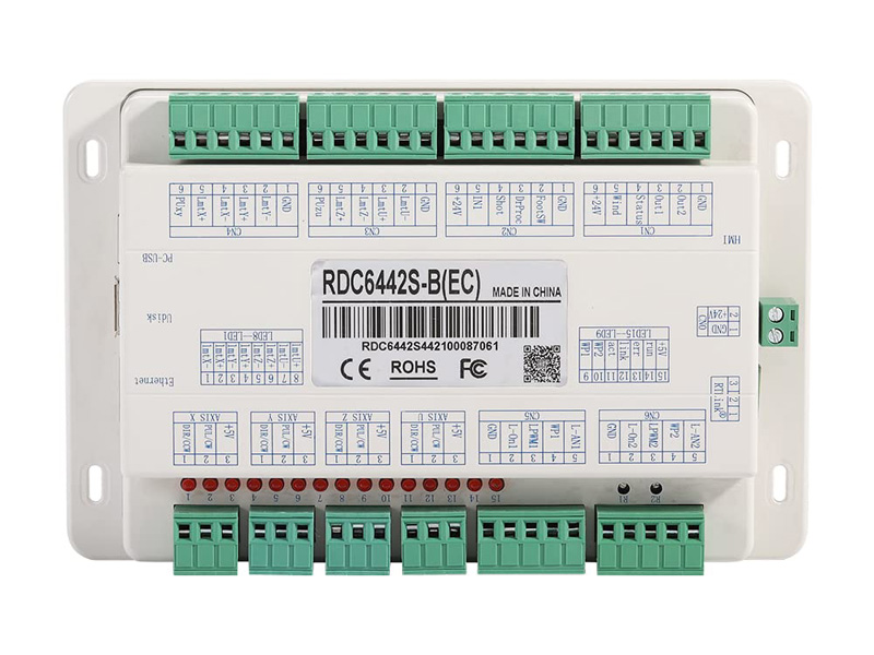
The first step is the motion control system. I use the RDC6442S-B (EC) laser motherboard. This control motherboard can control four axes, namely X, Y, Z, and U. The motherboard comes with an interactive display screen. The running state of the machine, the storage of processing files, and the debugging of the machine can be completed through the operation screen, but one thing to note is that the motor control parameters of the XYZ axis need to be connected to the computer for parameter setting.
For example: no-load acceleration and deceleration, cutting acceleration and deceleration, no-load speed, motor position error correction, laser type selection. The control system is powered by 24V DC, which requires a 24V switching power supply. In order to ensure the stability of the system, two 24V switching power supplies are used, one 24V2A directly supplies the motherboard, and the other 24V15A supplies power to three motors, while the 220V input terminal is connected with a 30A filter to ensure the stable operation of the system.
Control System Test
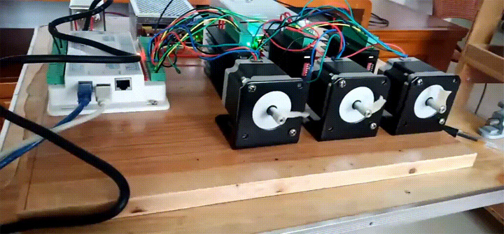
After the parameters are set, you can connect the motor for idling test. At this stage, you can verify the motor connection line, motor direction, screen operation direction, stepper motor subdivision settings, import cutting files for trial operation. The motor I chose is a two-phase 57 stepper motor with a length of 57mm, because there were just 3 left in the previous project, so I used it directly with the idea of not wasting it. The driver I chose is TB6600, which is an ordinary stepper motor. Into the motor driver, the subdivision is set to 64.
If you want the laser cutting system to have better high-speed performance, you can choose a three-phase stepper motor, which has a larger torque and very good high-speed performance. Of course, after subsequent tests, it was found that the two-phase 57 stepper motor is fully capable of high-speed movement of the X-axis when laser scanning photos, so I will use it for the time being, and replace the motor if it needs to be upgraded later.
In terms of safety protection system, the overall circuit layout must be separated from high voltage and low voltage. When wiring, it is necessary to pay attention not to have crossovers. The most important point is that it must be grounded. Because when the high voltage passes through, the metal frame and the shell will generate induced electricity, and when the hand touches it, there will be a numb feeling. At this time, we must pay attention to effectively grounding, and the best grounding resistance is not more than 4 ohms (need to test the ground wire ), to prevent electric shock accidents, in addition, the main power switch also needs to add a leakage protection switch.
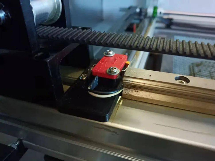
Limit Switch
The operation panel also needs to install an emergency stop switch, a power switch with a key, X, Y, Z axis limit switches for each motion axis, a constant temperature water protection switch for the laser tube, an emergency stop switch for cover opening protection to improve the safety of the laser cutter machine.
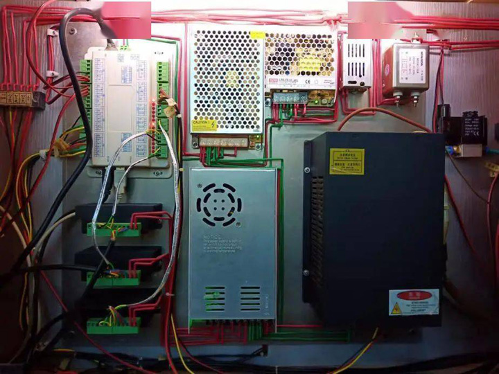
Circuit Layout
In order to facilitate subsequent maintenance, each terminal can be labeled accordingly.
Step 2. Mechanical Design
The second step is the design of the mechanical structure. This step is the focus of the entire laser cutting machine. The precision of the machine and the operation of the machine need to be realized by a reasonable mechanical structure. At the beginning of the design, the first problem faced is to determine the processing itinerary, and the formulation of the processing itinerary requires the initial guiding ideology. How much processing scope does it need?
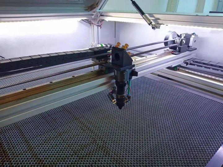
Mechanical Design
The size of a wood board is 1220mm*2400mm. In order to minimize the number of cutting boards, the width of the wood board is 1200mm as the length processing range, and the processing width must be greater than 600mm, so I set the width at about 700mm, and the length and width Each plus 60mm length for clamping or positioning. In this way, the actual effective processing range can be guaranteed to be 1200mm*700mm. According to the general estimation of the range of the processing itinerary, the overall size is close to 2 meters, which does not exceed the maximum range of 2 meters for express delivery, which meets the requirements.
Hardware Accessories
The next step is to purchase hardware accessories, laser head, one anti, two anti, synchronous pulley and so on. I chose the European standard 4040 thick aluminum profile for the main frame, because the installation accuracy of the XY axis determines the future processing accuracy, and the materials must be solid. The X-axis beam part of the laser head is made of 6040 thick aluminum profile, and the width is wider than the 4040 of the Y-axis, because when the laser head is in the middle position, the aluminum profile will deform if the strength is not enough.
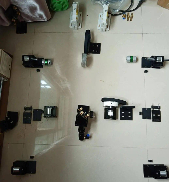
Hardware Accessories
XY Axis Structure Design
Before designing the XY axis structure, first measure and draw the hardware accessories and various parts, and then carry out the structural design through AutoCAD software.
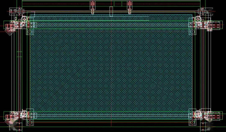
XY Axis Structure Design
The transmission of the X-axis is decelerated by the stepping motor through the synchronous pulley and output to the synchronous belt, and the open end of the synchronous belt is connected to the laser head. The rotation of the X-axis stepping motor drives the synchronous belt to move the laser head laterally; the transmission of the Y-axis is relatively It is a little more complicated. To make the left and right linear sliders move synchronously with one motor, two linear modules need to be connected in parallel with an optical axis, and then the optical axis is driven by a stepping motor to drive the two linear sliders at the same time, so as to move the Y axis. The X-axis can always be in a horizontal position.
Parts Processing & Assembly
After completing the design, the next step is to process and assemble the parts, process the X-axis spacer, 3D print the Y-axis optical axis bracket, assemble the aluminum profile frame, install the linear guide, etc. The most critical and tedious part is the adjustment of the accuracy. This process requires repeated debugging and requires patience.
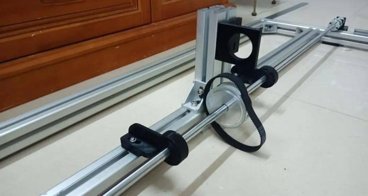
Y Axis Is Connected To The Optical Axis
1. The optical axis is fixed by 2 couplings and optical axis brackets.
2. Process the X-axis backing plate to connect the X-axis aluminum profile with the two linear modules of the Y-axis.
3. During the installation of the XY axis aluminum profile frame, the verticality and parallelism of the frame must be ensured during this process, so repeated measurements are required during the process to ensure accurate dimensions. When installing the two linear guides on the Y-axis, make sure that the guides are parallel to the aluminum profile, and measure by a dial indicator to ensure that the parallelism is within 0.05mm.
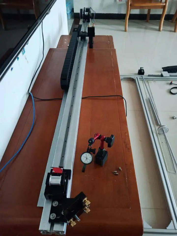
Install X-Axis Laser Head, Linear Guide, Tank Drag Chain And Stepper Motor
4. When installing the linear guide rail, it is necessary to ensure that the guide rail is parallel to the aluminum profile. The guide rail of each section needs to be measured by a dial indicator to ensure that the parallelism is within 0.05mm, which lays a good foundation for the subsequent installation.
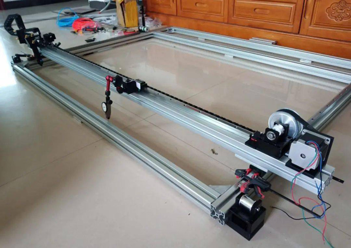
Fix The X-Axis Position
5. To install the Y-axis synchronous belt, first ensure that the X-axis is in a horizontal state, and use a dial indicator to mark the meter. After measurement, it is found that the aluminum profile itself has a curvature of about 0.05mm, so the horizontal accuracy should be controlled within 0.1mm (preferably The two dial indicators are reset to zero), and the position of the two sliders and the X-axis is fixed with a clip.
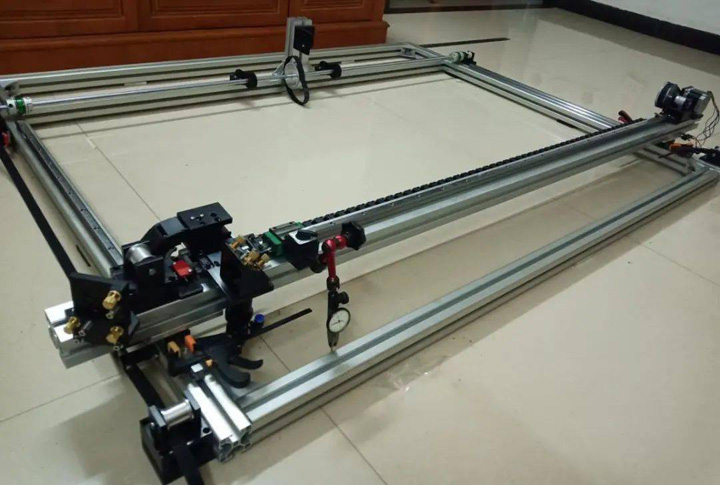
Thread The Timing Belts On Both Sides
6. Pass the timing belt on both sides and fix the timing belt on the left. Then reset the left contact dial indicator to zero, measure the horizontal error on the other side, adjust the horizontal error to within 0.1mm, and fix it with a clip. Then fix the right synchronous belt. At this time, due to the installation operation on the right side, the horizontal error will definitely increase. Then move the dial indicator to the left side again to zero, and loosen the right coupling to move the X axis. Slide the slider, adjust the horizontal error to within 0.1mm, and fix the torque coupling with a clip.
7. Now you can loosen the clamps on both sides, test whether the X axis is in a horizontal position when the Y axis moves, twist the Y axis synchronization wheel, and repeat the previous measurement process. If it is found that the X-axis is out of synchronization, it may be that the tightness of the synchronous belt is different on both sides or the accuracy of each structure has not been adjusted properly, then you need to go back to the previous stage and readjust it again. As long as the tightness of the synchronous belt is adjusted, the X-axis should be re-adjusted again until the Y-axis is moved, and the X-axis is always within the horizontal error range of 0.1mm. Remember to be patient at this stage.
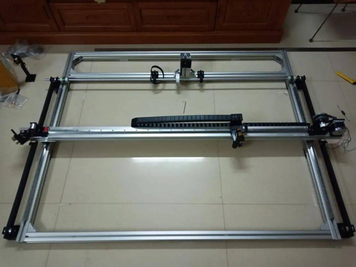
Adjust The XY Axis Frame
8. Check whether the tightness of the timing belts on both sides is consistent, and it is advisable to press down gently to a depth of 1-2cm, so that the depths on both sides are consistent.
9. Install the stepper motor. When installing the motor, you need to pay attention to adjusting its tightness. If the synchronous belt is too loose, it will cause the movement backlash, and if it is too tight, the synchronous belt will crack.
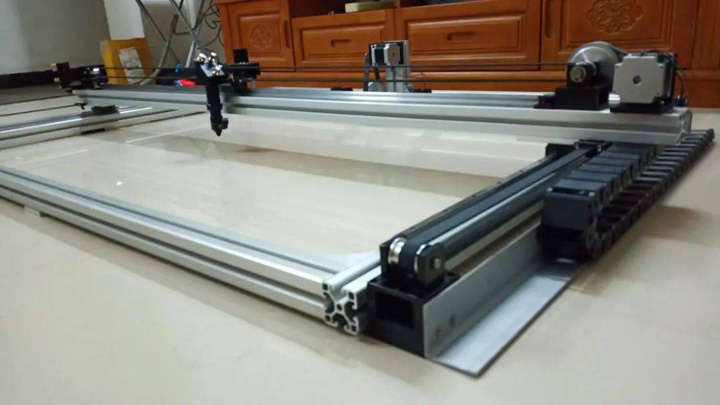
Install The Y-Axis Stepper Motor
Test The Mechanical Mechanism Stability
Connect the control system to test the stability of the mechanical structure, connect the computer to debug the motor parameters, measure the deviation between the drawn graph and the design size, adjust the pulse amount of the stepper motor according to the actual distance deviation, and check whether there is a backlash gap in the mechanism. Whether each stroke is coherent and whether the intersection points are connected. Repeated drawing is carried out, and the repeated positioning accuracy is detected by repeated drawing. Of course, the repeated positioning accuracy of the mechanism can be detected by means of a fixed dial indicator and a meter.
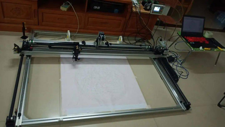
Connect The Control System For Testing
After repeating the drawing three times, you can see that all the strokes are a place without any ghosting, indicating that the relocation is OK. At present, the XY axis can already draw graphics. If the pen-lifting function is added, it can become a large-scale plotter. Of course, the real purpose is to make a laser cutter machine, so we need to continue to work hard.
After the XY axis is completed, the next step is to make the Z axis. Before making the Z axis, we need to do 3D modeling and design the overall frame. Because the Z axis is connected with the cutting platform and fixed on the frame module, it must be designed and manufactured together. The Z axis realizes the rising and falling functions, and then the XY axis module is directly placed on it, and the combination can realize the function of the XYZ axis.
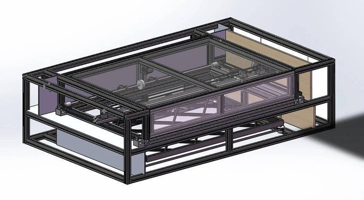
Design Z-Axis Lift Platform
Using Solidworks modeling, design the overall frame and Z-axis structure of the laser cutting table. Through the 3D perspective, structural problems can be quickly discovered and corrected quickly.
Moveable Platform Building
With the frame and structure in place, the moveable platform at the bottom of the machine can be made. The entire laser cutter machine is placed on the platform. The machine is relatively large. It is unrealistic to build the laser cutting table and then move it up. The process will also affect the accuracy of the machine, so it can only be built on the bottom mobile platform.
1. Now start building the moveable platform at the bottom, first buy the 5050 thickened square steel for making the frame.
2. The square steel is welded one by one, and it is very strong after completion, and there is no problem with the whole person sitting on it.
3. Weld 4 rollers to the frame and leave a 600mm gap on the left side. The main purpose is to reserve space for constant temperature water and air pump. Now that the frame of the mobile platform has been welded, it is necessary to install a layer of wood on the top and bottom.
4. Build the frame of the machine and buy aluminum profiles from the Internet. The model is 4040 national standard aluminum profiles. The main reason for using this national standard aluminum profile is that it is relatively light in weight, easy to handle after installation, has good strength, and the rounded corners around it are relatively small to facilitate the design and installation of subsequent sheet metal panels.
To build a machine frame in the living room, it is too large to fit.
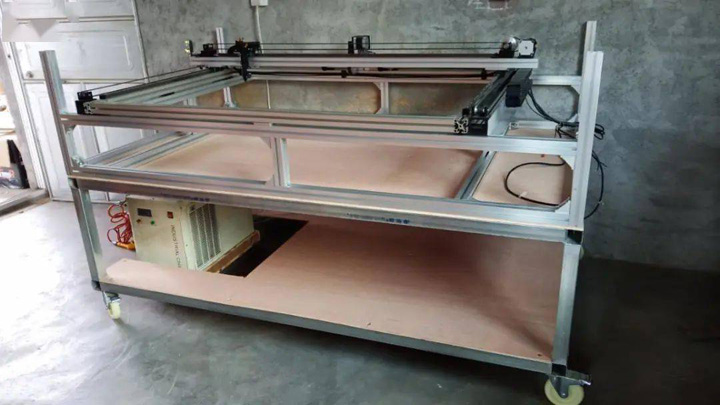
Assemble XY Axis And Machine Frame
5. Assemble the XY axis and the machine frame, put the completed frame on the mobile platform, and then install the debugged XY axis on the machine frame. The overall effect is still good.
6. Start to make the Z-axis support sheet, scribe the aluminum sheet, and determine the hole position. Do some drilling and tapping to make 4 identical support sheets.
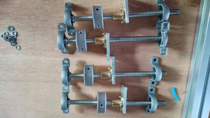
Assemble The Z-Axis Lift Screw
7. Assemble the Z-axis lifting screw, and assemble the T-shaped screw, synchronous pulley, bearing seat, support plate, and flange nut.
8. Install the Z-axis lifting screw, stepper motor, and timing belt. The principle of Z-axis lifting: The stepping motor tightens the synchronous belt through the tensioning wheels on both sides. When the motor rotates, it drives the four lifting screws to rotate in the same direction, so that the four supporting points move up and down at the same time, and the cutting platform is connected to the supporting points at the same time. Movement up and down. When installing the honeycomb panel, you need to pay attention to the adjustment of the flatness. Use a dial indicator to measure the height difference of the entire frame, and adjust the height difference to 0.1mm.
Mechanical structures such as air path structure, laser light path, and sheet metal skin will be explained in detail later when the corresponding system is involved. Next, the third part will be introduced.
Step3. Laser Tube Control System Setup
1. Choose the CO2 laser tube model. The laser tube is divided into two types: glass tube and radio frequency tube. The RF tube adopts 30V low voltage with high precision, small spot and long life, but the price is expensive, while the life of the glass tube is about 1500 hours, the spot is relatively large, and it is driven by high voltage, but the price is cheap. If you only cut wood, leather, acrylic, Glass tubes are fully competent, and most of the laser cutters on the market currently use glass tubes. Due to the cost issue, I choose glass tube, the size of 1600mm*60mm, the laser tube cooling needs to use water cooling, and it is constant temperature water.
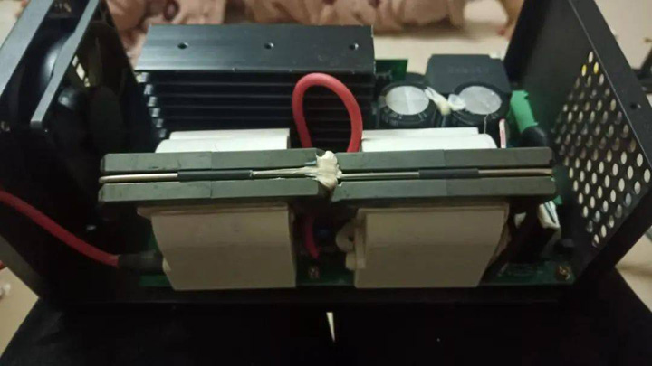
Laser Power Supply
The laser tube power supply I chose is the 100W laser power supply. The function of the laser power supply is introduced. The positive electrode of the laser tube emits a high voltage of nearly 10,000 volts. Due to the high-concentration CO2 gas in the high-voltage discharge excitation tube, a laser with a wavelength of 10.6um is generated at the tail of the tube. Note that this laser is invisible light.
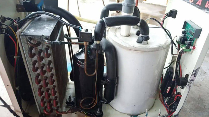
CW5000 Water Chiller
2. Choose water chiller. The laser tube will generate high temperature during normal use, and it needs to be cooled by water circulation. If the temperature is too high and not cooled in time, it will cause irreversible damage to the laser tube, resulting in a sharp drop in life or bursting of the laser tube. The speed at which the water temperature drops also determines the performance of the laser tube.
There are two types of water cooling, one is air cooling, and the other is the cooling method using air compressor cooling. If the laser tube is about 80W, air cooling can be competent, but if it exceeds 80W, the compressor cooling method must be used. Otherwise, the heat cannot be suppressed at all. The constant temperature water I choose is the CW5000 model. If the power of the laser tube is upgraded, this constant temperature water can still be competent. The whole machine includes a temperature control system, a water storage bucket, an air compressor, and a cooling plate. module composition.
3. Install the laser tube, install the laser tube on the tube base, adjust the height of the laser tube to make it consistent with the design height, and pay attention to handling it with care.
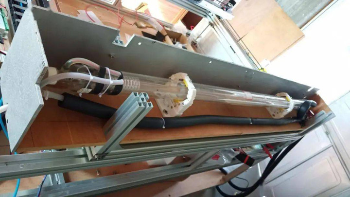
Laser Tube Installation
Connect the constant temperature water outlet pipe. It should be noted that the water inlet first enters from the positive pole of the laser tube, the positive water inlet of the laser tube should face down, the cooling water enters from the bottom, and then comes out from the top of the negative pole of the laser tube, and then returns to the return through the water circulation protection switch. The constant temperature water tank completes a cycle. When the water cycle stops, the water protection switch is disconnected, and the feedback signal is sent to the control board, which turns off the laser tube to prevent overheating.
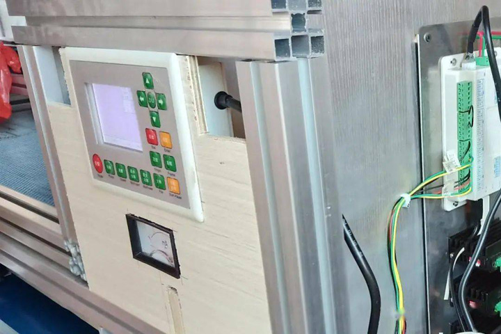
Connect The Ammeter
4. The negative pole of the laser tube is connected to the ammeter, and then back to the negative pole of the laser power supply. When the laser tube is working, the ammeter can display the current of the laser tube in real time. Through the numerical value, you can compare the set power and the actual power to judge whether the laser tube is working normally.
5. Connect the circuit of the laser power supply, constant temperature water, water protection switch, ammeter, and prepare protective glasses (because the laser tube emits invisible light, you need to use 10.6um special protective glasses), and set the power of the laser tube to 40 %, turn on the burst mode, place the test board in front of the laser tube, press the switch to emit the laser, the board is instantly ignited, and the test effect is very good.
The next step is to adjust the optical path system.
Step 4. Laser Tube Light Guide System Setup
The fourth part is the laser tube light guide system setup. As shown in the figure above, the laser light emitted by the laser tube is refracted by a mirror to 90 degrees to the second mirror, and the second mirror is refracted again by 90 degrees to the third mirror. Refraction causes the laser to shoot downward toward the focusing lens, which then focuses the laser to form a very fine spot.
The difficulty of this system is that no matter where the laser head is in the machining process, the focused spot must be at the same point, that is to say, the optical paths must be coincident in the moving state, otherwise the laser beam will be deflected and no light will be emitted.
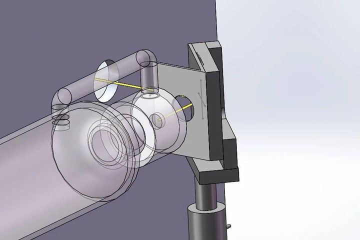
The First Surface Mirror Optical Path Design
The adjustment process of the mirror bracket: the mirror and the laser are at a 45-degree angle, which makes it difficult to judge the laser point. It is necessary to 3D print a 45-degree bracket for auxiliary adjustment, paste the textured paper on the through hole, and the laser is turned on. Spot shooting mode (on time 0.1S, power 20% to prevent penetration), adjust the height, position and rotation angle of the bracket, so that the light spot is controlled in the center of the round hole.
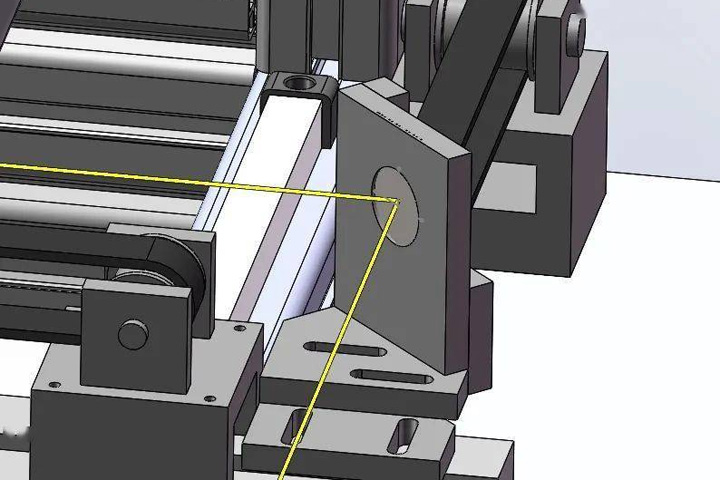
The Second Surface Mirror Optical Path Design
The precise installation position and installation height of the second mirror bracket are obtained through the 3D design of the second surface mirror path, and the second surface mirror bracket is accurately installed by measuring the vernier caliper (install it to the initial position first).
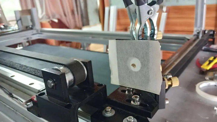
Adjust The Reflection Angle Of The First Surface Mirror
The process of adjusting the angle of the first surface mirror: move the Y-axis close to the mirror, laser dot, then move the end of the Y-axis away, and dot again. At this time, it will be found that the two points do not coincide, if the near point is higher and the far point is lower, then the mirror needs to be adjusted to rotate upwards, and vice versa; the next step is to continue to make points, far and near, if the near point is to the left and the far point is to the right, you need to adjust the mirror to rotate to the left, and vice versa, until the near point coinciding with the far point as a point, it means that the optical path of the second surface mirror is completely parallel to the movement direction of the Y-axis.
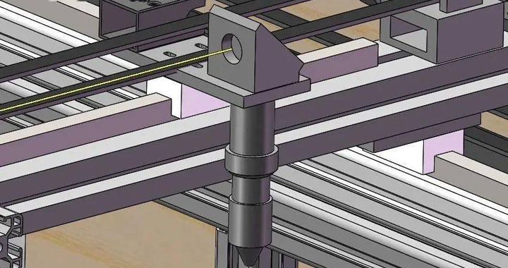
The Third Surface Mirror Optical Path Design
The process of adjusting the angle of the second surface mirror: move the Y-axis to the first surface mirror, then move the X-axis to the near end, do laser dots, then move the X-axis to the far end, and then do the laser dots, at this time, observe whether the near point is higher and the far point is lower , you need to adjust the second surface mirror to rotate up, and vice versa. In the next step, continue to make points, one point far and one near, if the near point is to the left and the far point is to the right, you need to adjust the second surface mirror to rotate to the left, and vice versa, until the near point and the far point coincide as one point, which means that the optical path of the near-end third surface mirror is completely parallel to the movement direction of the X-axis. Then move the Y-axis to the far-end, and mark a point at the near-end and the far-end of the X-axis, if they do not coincide it means that the two mirror paths do not overlap, and it is necessary to return to adjust the angle of the first surface mirror until the two points on the X-axis at the near end of the Y-axis and the two points and four points on the X-axis at the far end of the Y-axis are completely coincident.
In fact, the adjustment is not over at this step. Observe whether the light spot of the third surface mirror lens holder is in the center of the circle. When the light spot is to the left, the second surface mirror lens holder needs to be moved back, and vice versa. Adjust the position of the entire laser tube to move down, and vice versa. When changing the second surface mirror bracket, we need to repeat the process of adjusting the angle of the second surface mirror lens again. When changing the height of the laser tube, we need to repeat the entire lens adjustment process One pass (including: the adjustment process of the first surface mirror bracket, the first mirror lens and the second surface mirror), and do the dots again until the light spot is in the center position and the four points are completely coincident.
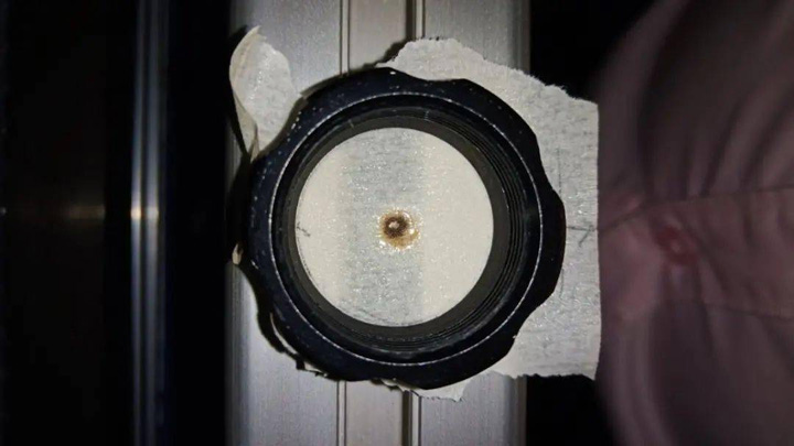
Adjust The Reflection Angle Of The Third Surface Mirror
The adjustment process of the angle of the third surface mirror: the adjustment of the mirror is to add two points of the Z-axis lifting and lowering on the basis of the mirror, that is, 8 points. The adjustment principle is to first determine the lifting point of the four points and then move the X Axis to the other end, and then hit the lift point. If the high point of the light spot is higher than the low point, you need to rotate the third surface mirror lens backward, and vice versa. Rotate to the right and vice versa.
If the light spot can not always be adjusted to coincide, it means that the third surface mirror optical path does not coincide with the X-axis, and it is necessary to return to adjust the angle of the second surface mirror lens. It is necessary to return to adjust the height of the laser tube, and then start from a reverse bracket to adjust it again until the 8 points are completely coincident.
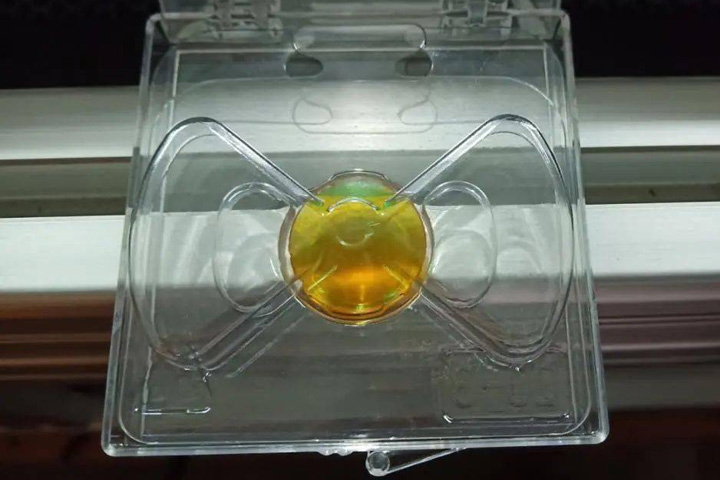
Focusing Lens
There are four types of focusing lens: 50.8, 63.5, 76.2, and 101.6. I chose 50.8mm.
Put the focusing lens into the cylinder of the laser head, with the convex side facing up, place a sloping wooden board, move the X-axis to make a point every 2mm, find the position with the thinnest spot, measure the distance between the laser head and the wooden board, this distance It is the most suitable focal length position for laser cutting, and the optical path has been adjusted at this step.
Step 5. Blow Exhaust System Setup
The fifth part is the air blowing and exhaust system setup. Thick smoke will be generated during laser cutting, and the thick smoke particles will cover the focusing plate and reduce the cutting power. The solution is to increase the air pump in front of the focusing plate.
The air pump I choose is the air compressor air pump, the main reason is that the air pressure is relatively high, and the cutting efficiency can be increased due to the action of the gas during cutting. The output signal is connected from the main board to control the solenoid valve, and the solenoid valve controls the air pump to blow air.
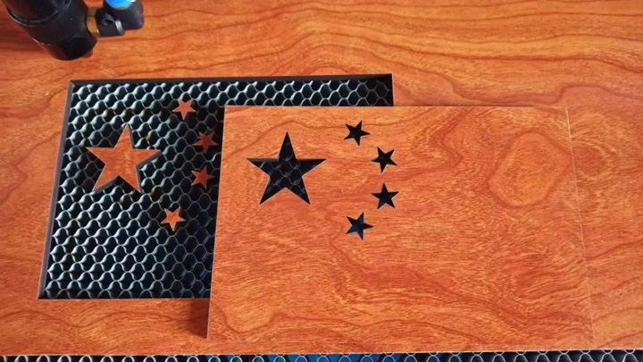
Laser Cut Wood Projects
After installation, I can't wait to make a trial cut of the 6mm multi-layer board, which can be cut through smoothly, and the effect is very ideal. The only problem is that the exhaust system is not completed, and the smoke is relatively large.
Cut the stainless steel plate according to the design size, and fix the stainless steel plate with screws after drilling. The whole machine is completely closed, leaving only the air inlet and air outlet.
The exhaust fan is fixed on the wall, and a bracket needs to be made.
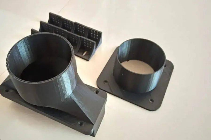
3D Printed Air Outlet
The medium pressure fan uses a 300W power, a rectangular air outlet specially designed according to the size of its own aluminum alloy window.
Step 6. Lighting and Focusing Systems Setup
The sixth part is the lighting and focusing system, which uses an independent power supply 12V LED light strip, and LED lighting is added to the control system part, processing area, and storage area at the same time.
A cross laser head is added behind the laser head for focusing. It uses a 5V independent power supply and is equipped with an independent switch. The position of the laser head is determined by the cross line. The horizontal laser line is used to judge the depth of the board. The center indicates that the board is not flat or the focal length is not adjusted properly, you can adjust the Z axis up and down focus, and adjust the horizontal line to the center.
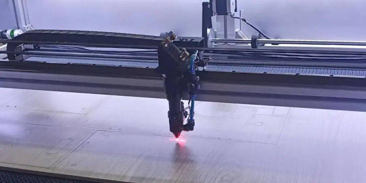
Install Laser Cross Focus
Setp 7. Operational Optimization
The seventh part is operation optimization. In order to facilitate emergency stop, the emergency stop switch is designed at the top close to the work surface, and a key switch, USB interface and debugging port are installed on the side. The front is designed with the main power switch, air blowing and exhaust control switch, LED lighting switch, laser focus switch, which enables all operations to be completed under one panel.
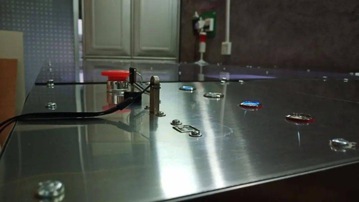
Switch Button Layout
Cabinet doors are designed on both sides of the machine, the left side is used to store the tools used by the laser cutter, and the right side is used for inspection and maintenance. There is an inspection window at the bottom of the front. When a workpiece is dropped, it can be taken out from the bottom. You can also observe whether the laser power is enough and whether it has been cut through in time, so as to increase the power in time.
I also added a foot pedal. When you need to start the laser cutter, you only need to step on the foot pedal to complete the operation, which saves the tedious button operation, which is very fast and convenient.
Step 8. Test and Debug
Finally, it is necessary to test the functions of the laser cutting system, improve the cutting parameters in the process of use to achieve better results, and debug the functions of laser cutting and laser engraving.
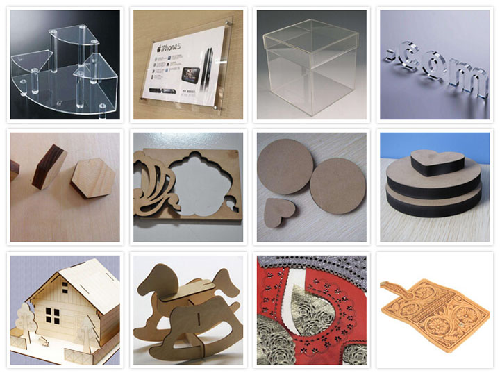
Laser Cut Projects
At this point, the entire laser cutter machine has been finished building. Some bottlenecks and difficulties encountered in the making process have been overcome one by one through hard work. This DIY experience is very valuable. Through this project, I have learned a lot about laser cutting machines. At the same time, I am very grateful for the help of the industry leaders, which made the project less detours.
