What Is A CNC Machine?
A CNC machine is an numerical control machine tool with the added feature of an on board computer. The computer is referred to as the machine control unit (MCU). The numerical data required to produce a part is provided to the machine in the form of program. The program is translated into the appropriate electrical signals for input to motors that run the machine.
The machine frame bed is the mechanical structure of the CNC machine, and it is also composed of the main drive system, feed drive system, bed, workbench and auxiliary motion devices, hydraulic and pneumatic systems, lubrication systems, cooling devices, chip removal, protection systems and other parts. But in order to meet the requirements of numerical control and give full play to the performance of the machine tool, it has undergone great changes in the overall layout, appearance, structure of the transmission system, tool system and operating performance. The mechanical parts of CNC machines include bed, box, column, guide rail, worktable, spindle, feed mechanism, tool exchange mechanism.
How Does A CNC Machine Work?
CNC machines use computers to realize the technology of digital program control. This technology uses a computer to execute the sequential logic control function of the movement track of the device and the operation of the peripherals according to the control program stored in advance. As a computer is used to replace the original numerical control device composed of hardware logic circuits, the storage, processing, calculation, logical judgment and other control functions of the input operation instructions can be realized by computer software, and the micro-instructions generated by the processing can be transmitted. Drive the motor or hydraulic actuators to the servo drive device to drive the CNC machine to run.
In order to run a CNC machine, you can go through the following steps:
Step 1. According to the drawing and process plan of the machined part, use the specified code and program format to program the movement path of the tool, the processing process, the process parameters, and the cutting amount into the instruction form that can be recognized by the CNC system, that is, to write the processing program.
Step 2. Input the programmed processing program into the CNC device.
Step 3. The CNC device decodes and processes the input program (code), and sends corresponding control signals to the servo drive device and auxiliary function control device of each coordinate axis to control the movement of each part of the machine tool.
Step 4. In the movement process, the CNC system needs to detect the coordinate axis position of the CNC machine, the state of the travel switch, etc. at any time, and compare it with the requirements of the program to determine the next action until a qualified part is processed.
Step 5. The operator can observe and check the processing conditions and working status of the CNC machine at any time. If necessary, it is necessary to adjust the CNC machine action and processing program to ensure the safe and reliable operation of the machine tool.
Cartesian Coordinate System
Almost everything that can be produced on a conventional machine tool can be produced on a computer numerical control machine tool, with its many advantages. The machine tool movements used in producing a product are of two basic types: point-to-point (straight-line movements) and continuous path (contouring movements).
The Cartesian, or rectangular, coordinate system was devised by the French mathematician and philosopher Rene’ Descartes. With this system, any specific point can be described in mathematical terms from any other point along three perpendicular axis. This concept fits machine tools perfectly since their construction is generally based on three axis of motion (X, Y, Z) plus an axis of rotation. On a plain vertical milling machine, the X axis is the horizontal movement (right or left) of the table, the Y axis is the table cross movement (toward or away from the column), and the Z axis is the vertical movement of the knee or the spindle. CNC systems rely heavily on the use of rectangular coordinates because the programmer can locate every point on a job precisely. When points are located on a workpiece, two straight intersecting lines, one vertical and one horizontal, are used. These lines must be at right angles to each other, and the point where they cross is called the origin, or zero point (Fig. 1)
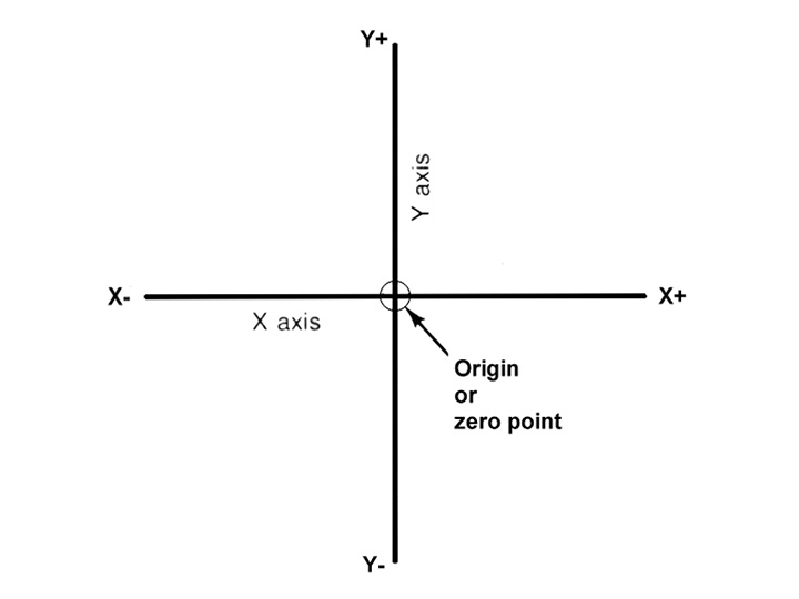
Fig. 1 Intersecting lines form right angles and establish the zero point.

Fig. 2 The three-dimensional coordinate planes (axis) used in CNC.
The three-dimensional coordinate planes are shown in Fig. 2. The X and Y planes (axis) are horizontal and represent horizontal machine table motions. The Z plane or axis represents the vertical tool motion. The plus (+) and minus (-) signs indicate the direction from the zero point (origin) along the axis of movement. The four quadrants formed when the XY axis cross are numbered in a counterclockwise direction (Fig. 3). All positions located in quadrant 1 would be positive (X+) and positive (Y+). In the second quadrant, all positions would be negative X (X-) and positive (Y+). In the third quadrant, all locations would be negative X (X-) and negative (Y-). In the fourth quadrant, all locations would be positive X (X+) and negative Y (Y-).
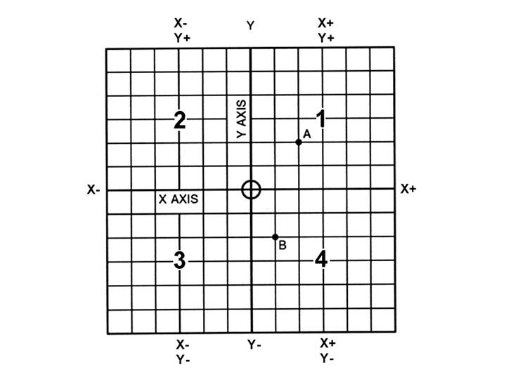
Fig. 3 The quadrants formed when the X and Y axis cross are used to accurately locate points from the X/Y zero, or origin point.
In Fig. 3, point A would be 2 units to the right of the Y axis and 2 units above the X axis. Assume that each unit equals 1.000. The location of point A would be X + 2.000 and Y + 2.000. For point B, the location would be X + 1.000 and Y - 2.000. In CNC programming it is not necessary to indicate plus (+) values since these are assumed. However, the minus (-) values must be indicated. For example, the locations of both A and B would be indicated as follows:
A X2.000 Y2.000
B X1.000 Y-2.000
A computer system is connected to the machine comprising of sensors and electrical drives. The program controls the machine axis' movements.
What Are The Most Common Types of CNC Machines?
Early machine tools were designed so that the operator was standing in front of the machine while operating the controls. This design is no longer necessary, since in CNC the operator no longer controls the machine tool movements. On conventional machine tools, only about 20 percent of the time was spent removing material. With the addition of electronic controls, actual time spent removing metal has increased to 80 percent and even higher. It has also reduced the amount of time required to bring the cutting tool into each machining position.
There are 10 most common types of CNC machines that present in a variety of industries.
1. CNC Milling Machines (CNC Mills)
2. CNC Router Machines (CNC Routers)
3. CNC Laser Machines (Laser Cutters, Laser Engravers, Laser Welders)
4. CNC Lathe Machines (CNC Lathes)
5. CNC Drilling Machines (CNC Drills)
6. CNC Boring Machines
7. CNC Grinding Machines (CNC Grinders)
8. Electrical Discharge Machines (EDM)
9. CNC Plasma Cutting Machines (CNC Plasma Cutters)
10. 3D Printers

