Introduction
I'm skeptical that someone could make a desktop laser engraver kit with two used DVD-ROMs (CD-ROMs and DVD-RW for option) and a few small parts. So I did it myself, which lasted 5 days (including the time to buy things and other express delivery), and finally DIY a laser engraver kit. Quite a sense of achievement, now I will teach you hands-on.
There are various articles on the Internet on the use of waste optical drives to modify laser engravers and laser cutters, but the existing articles are either unclear, or the cost is high and there are many tools. This article integrates resources, chooses the best solution, and uses a simple and low-cost modification method for reference only.
Here I'm going to show how to make a simple laser engraving machine using a DVD-ROM disassembled from an old desktop computer, which uses Arduino as the main controller and GRBL software to control the movement of the stepper motors and the operation of the laser module , can be used to engrave and cut wood, paper, leather, acrylic, and plastic.
List Of Items
All the items that may be needed have been considered here as much as possible. Except for goggles, other tools are not necessary. They are used in the building process, so they are listed by the way.
Components List
| Item | Quantity | Remark |
| Arduino Control Board | 1 | |
| CNC Shield V3 | 1 | |
| A4988 Drive Module | 2 | DRV8255 can also be used, A4988 is enough, these two drivers can be directly inserted into CNC Shield V3. |
| DVD-ROM | 2 | Some people also use a DVD-RW to change the laser head, but it requires strong hands-on ability. It is not recommended for beginners to use it. |
| 250mV 650nm Laser | 1 | |
| 12mm Laser Radiator | 1 | |
| MOS Trigger Switch Driver Module | 1 | Convert PWM signal to laser voltage. |
| 12V Power | 1 | Lithium battery or 12V power matcher can be used. |
Required Tools
1.Multimeter.
2.Soldering Iron.
3.Glue Gun.
4.Mini Electric Grinder.
5.650nm Laser Goggles (Laser can cause irreversible damage to the eyes, make sure everyone wears laser goggles before turning on the laser power, and make sure that the goggles can protect the 650nm laser wavelength).
DIY Steps
Step 1. Disassemble The DVD-Rom
1.1. All you need in a DVD-Rom drive is the stepper motor assembly and the laser diode. I had no luck finding out that my DVD-Rom came with a very difficult plastic component to work with. So I took apart three DVD-Rom drives and only used parts from two. The disassembly process is quite difficult, and that's pretty much the case with most DVD-Rom drives I've ever opened.
1.2. After removing the screws on the bottom of the drive, you can lift it off like a cover. You'll most likely see two circuit boards under the bottom cover, both of which are useless to us. But remember to keep other useful parts for other crafting projects. For example there is a small DC motor worth staying under the front circuit board.
1.3. Now you should remove the front panel along with the front tray. The front panel comes loose when you pull the tray out (just use a hairpin and that little hole in the front panel).
1.4. The next steps will require removing the screws and perhaps some brute force. Remove both circuit boards. Be careful with the cables attached to the stepper motors. This motor needs to be removed.
1.5. If you place the DVD-Rom drive right side up and remove the top cover, you should find what we're looking for - a stepper motor assembly. Unscrew the screw and just take it out.
1.6. Now that we've got the stepper motor assembly out, it's time to do some cleaning. Remove the spindle motor, it might be useful, but I found it too cumbersome to drive, so I ditched them. They are usually held in place with three very small screws, although sometimes they are part of a larger assembly, so be careful not to break the two rods that support the lens when removing them.
1.7. As for the lens, just use the most suitable method to remove it, we need to leave a smooth surface, and then connect some other parts on it. Be careful not to damage the DVDR drive's laser diode.
Step 2. Solder The Stepper Motor Cable
In the disassembled structure, the position of the stepper motor is shown in the figure:
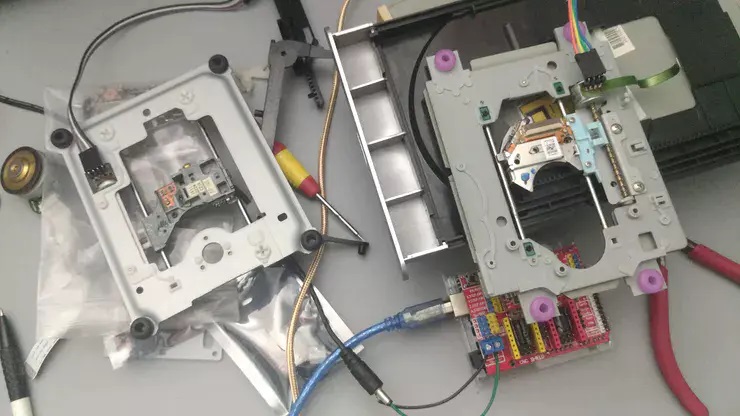
The stepper motors of different optical drives are different, so the line sequence is not easy to determine, but we can observe the cables drawn from the stepper motors, just follow the welding sequence of the cables. (The wiring problem is not considered first)
Step 3. Connect The Circuit
The circuit connection is as shown in the figure:
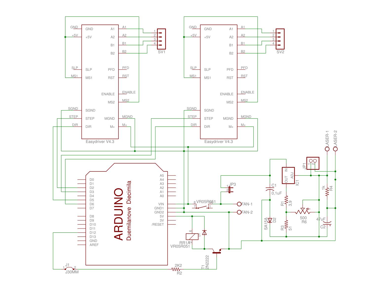
Adjust the multimeter to the on-off gear, and connect the positive and negative poles of the multimeter to two adjacent pins. The sound of the multimeter is the channel, that is, the same coil. This stepper motor is a four-wire two-phase stepper motor with two sets of coils, we just need to make sure.
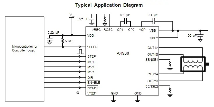
The A4988 stepper motor driver module that needs to be used in the project.
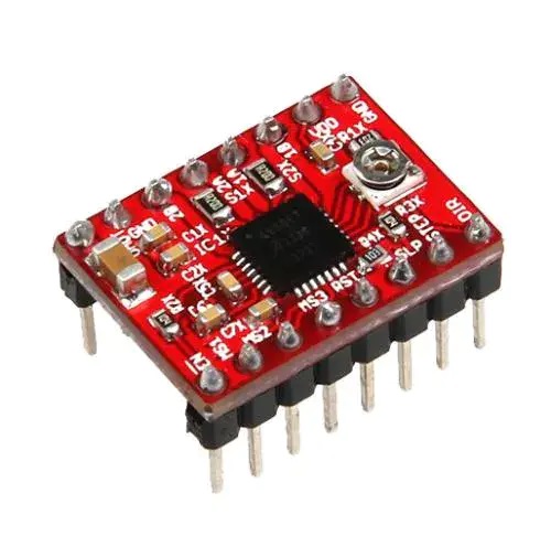
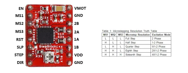
Pin definition and subdivision resolution configuration.
A4988 typical application circuit diagram.
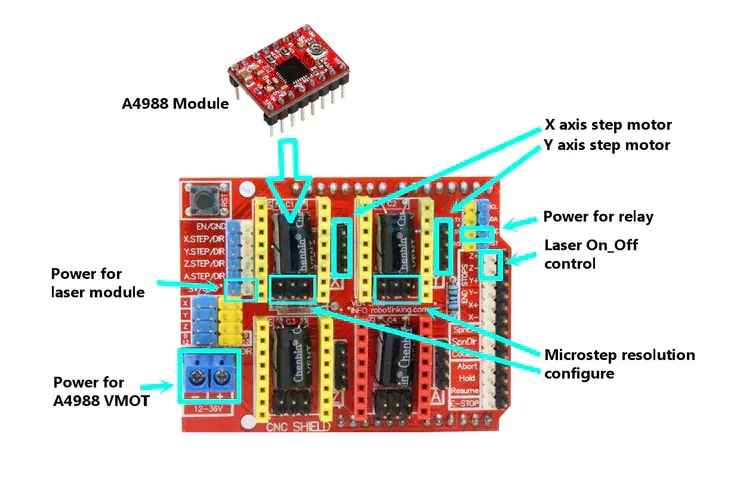
Pin definitions for CNC Shield V3 related functions.
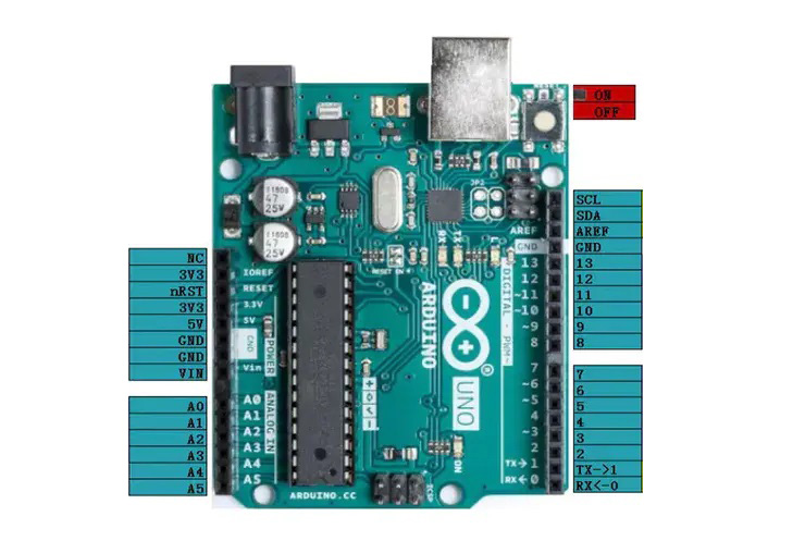
Pin definition of Arduino UNO R3. The green markers are the pin definitions for the Arduino and the purple pin definitions for the CNC Shield V3.
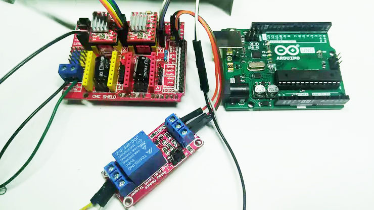
The following are the Arduino UNO R3, CNC Shield V3, and relay modules to be used. When installing, just plug the CNC Shield V3 into the corresponding interface socket of Arduino UNO R3.
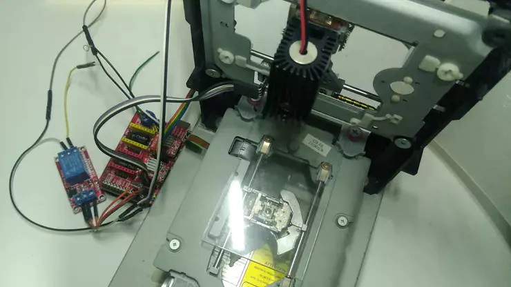
Install the X, Y axis stepper motor motion mechanism and the laser module on the previously prepared bracket.
Step 4. GRBL Firmware Burning
The firmware can be burned with XLoader, or compiled and uploaded with the Arduino IDE.
This work uses XLoader to burn, the GRBL firmware version number is grbl_v0_9j, other firmware versions are similar, please test by yourself.
Method 1: XLoader Burning
1. Prepare the XLoader burner, grbl_v0_9j.hex firmware.
2. The Arduino control board is connected to the computer USB serial port.
3. Open the XLoader burner, select grbl_v0_9j.hex , and click upload to burn.
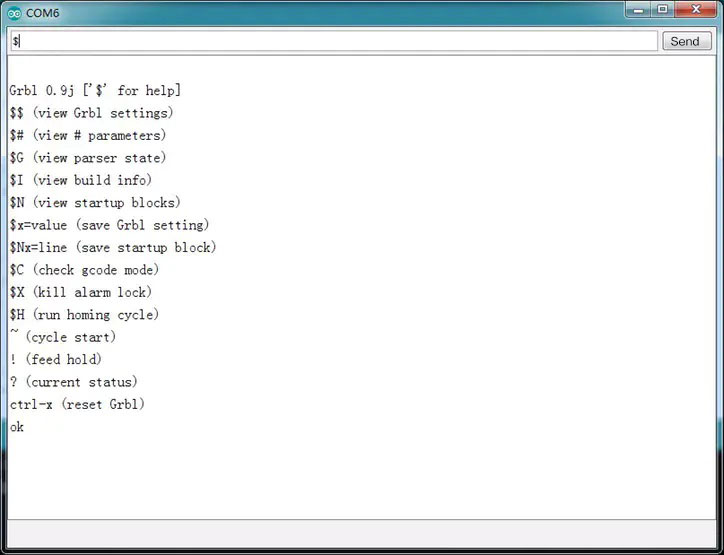
4. After the software is successfully programmed and powered on again, the following information will be output in the serial port. Note that the baud rate should be set to 115200.
Method 2: Arduino IDE Compilation
1.Download the grbl_v1_1h.zip archive on Github (https://github.com/gnea/grbl).
2.Open the Arduino IDE, select Project -> Load Library -> Add .ZIP Library, and select the downloaded compressed package.
3.Select File->Examples->grbl->grblUpload
4.Click the upload button to upload, the configuration file is in config.h, there is no need to modify it here, just use the default configuration.
Step 5. Firmware Test
After the firmware is uploaded successfully, you can set the firmware and open the GRBL host computer software CNCjs (CNCjs is used here as the test software, other GRBL control software is used in the same way, the purpose is to send g-code or setting instructions to the arduino, you can refer to learning use).
5.1. Connect Arduino.
5.2. Configuring the GRBL firmware.
Enter the following commands in the console:
$100 = 106.666 (x, step/mm) //Set the X-axis speed.
$101 = 106.666 (y, step/mm) //Set the Y axis speed.
$130 = 36.000 (x max travel, mm) //Set the X-axis maximum travel.
$131 = 36.000 (y max travel, mm) //Set the maximum travel of the Y axis.
5.3. Test the firmware.
Use the move button in the coordinate axis component to check whether the movement stroke is correct. If the movement stroke is not correct, adjust the movement rate of the X and Y axes.
Use the [Laser Test] and [Laser Off] in the laser assembly to test whether the laser can be turned on and off successfully (make sure to wear goggles before turning on the laser).
Step 6. Frame Structure
No other materials are used in the production here, and they are all built using discarded optical drive casings, so the laser etching machine frame is not complicated, and hot melt glue is used to connect. As long as the flexible movement of the X-axis and Y-axis is realized.
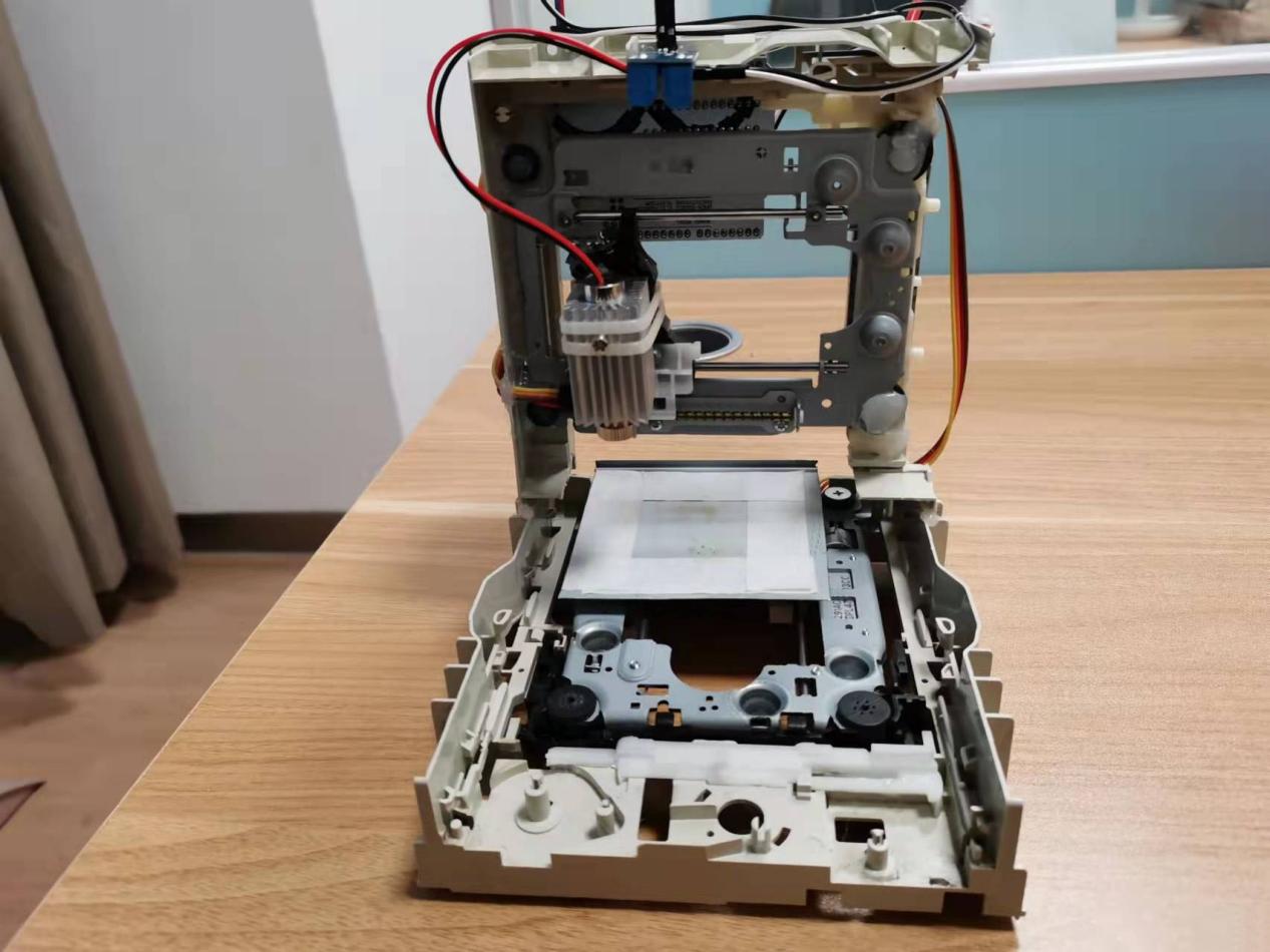
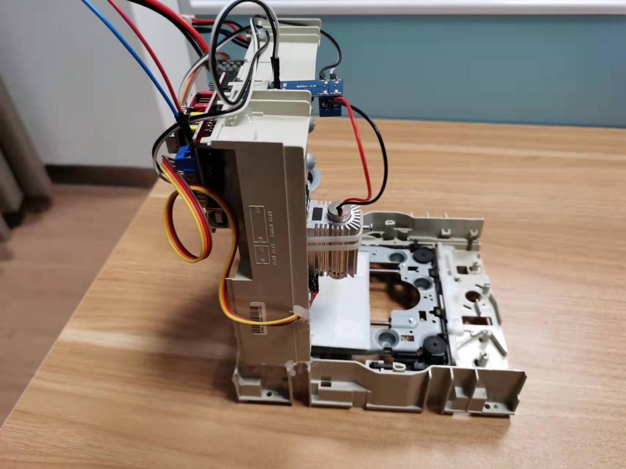
Prepare a suitable size of backing plate (the case of the optical drive is used here) and stick it on the bottom slider, use a cable tie to tie the laser head assembled with the heat sink to the left and right moving slider, the Y-axis here drives the backing plate moving back and forth, the X axis drives the laser head to move left and right.
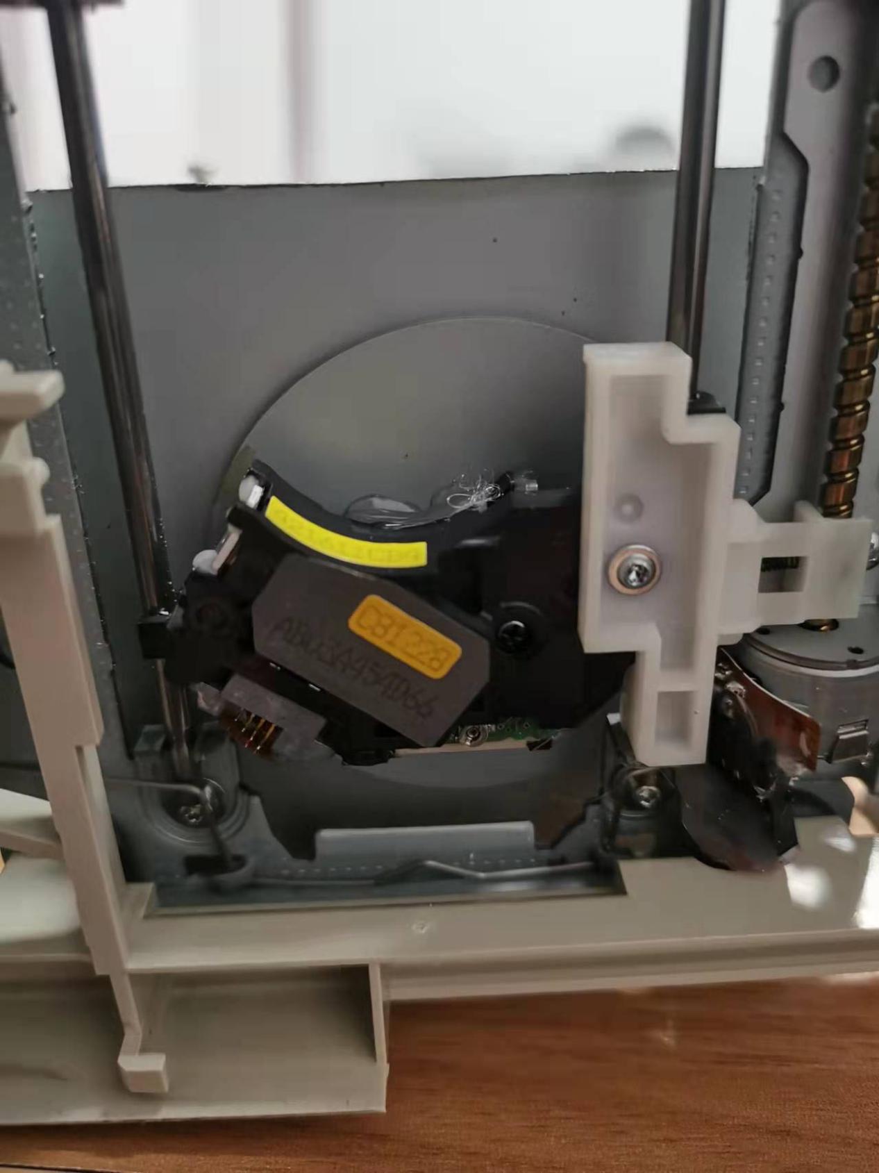
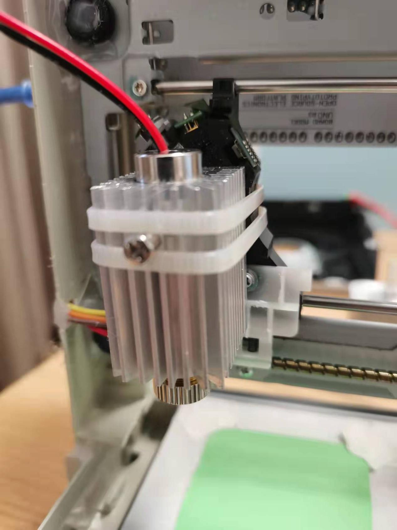
At this point, all the hardware parts are connected. If there is no accident, the laser engraving system can work normally.
Step 7. Engraving And Debugging
To engrave, you only need to load the G-code file into the upper computer software (CNCjs) and click to run. There are many ways to generate G-code, you can search by yourself.
Then comes the exciting time, with which you can print some of your favorite text or graphics on wood, MDF, plywood, acrylic, plastic, and other materials.
Things To Consider
1. Before deciding to leave, you need to be clear that the power of this laser engraving machine can only engrave acrylic, leather, and small wood chips that do not reflect red light such as blue, green or black. The stroke is 37mmX37mm. It can only be used for learning and testing, not for commercial use.
2. Say the important thing three times: make sure to wear goggles before turning on the laser power, and remind people around you to pay attention to the danger of laser engraving and cutting.
3. If the stepper motor is very hot, it is necessary to use a Phillips screwdriver to rotate the potentiometer on the A4988 driver to reduce the working current.
After reading the above content, do you think it is very simple to make such a laser engraver yourself? If you are interested in it, hurry up and make one too.

