In line with my own interests and hobbies, as well as the DIY spirit that money can't buy, I stumbled all the way, which lasted 15 days, and finally finished the CNC router DIY project at home.
In fact, I thought for a long time before doing it, whether each part can be done by myself, what kind of structure, accessories, setup, operation and so on. In this process, I also referred to the information of major technical forums, and I would like to thank these experts for their selfless dedication.
Before you start working, you must first understand how does a CNC router machine work. The popular self-made CNC router kit on the market is actually a type of numerical control system based on the parallel port of the computer. The software on the computer converts the G code into the control pulses of the stepping motors of each axis (usually three axes: X, Y, Z), and then outputs them directly through the parallel port.
Note: At this time, the parallel port is not used for parallel output data, it only outputs pulses. Therefore, the DIY CNC router plan includes the following four steps:
Step 1. Design Drawings for CNC Router
In order to DIY more efficiently and adjust, first of all, we must design drawings and determine the table size and specifications of each part of the CNC machine. It mainly includes dimension drawing of optical axis, dimension drawing of ball screw, dimension drawing of left and right support arms, dimension drawing of Y-axis moving base plate, dimension drawing of motor end of base (rear part), dimension drawing of front end of base, dimension drawing of X-axis moving base, Z-axis moving base dimension, dimension drawing of the top and bottom plates of the Z axis, and dimension drawing of the bearing seat of the Z axis.
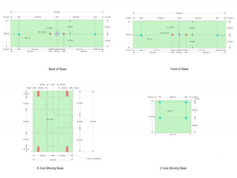
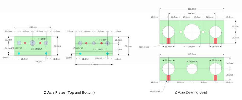
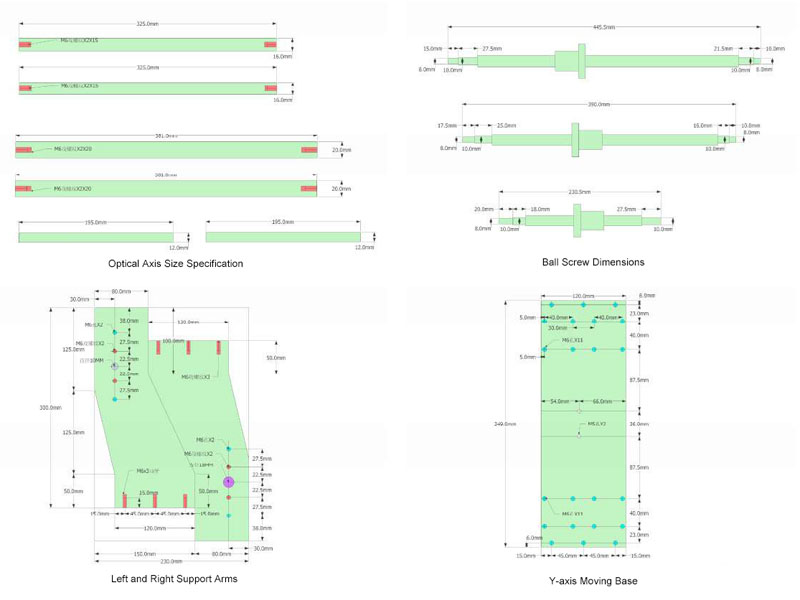
Drawings
When I design drawings, I always revise and modify them. I have designed 3 sets of drawings, and the size of the drawings was larger at first. Later, I finalized these 10 drawings for my DIY plan.
Step 2. Circuit Parts Design and Testing
After designing the drawings let's start preparing the circuit part.
1. Three 2A 60 stepping motors, the motor is 6 cores, the middle tap is not connected, and it is changed to 4 cores.
2. MACH3 control board.
3. 24V6.5 switching power supply.
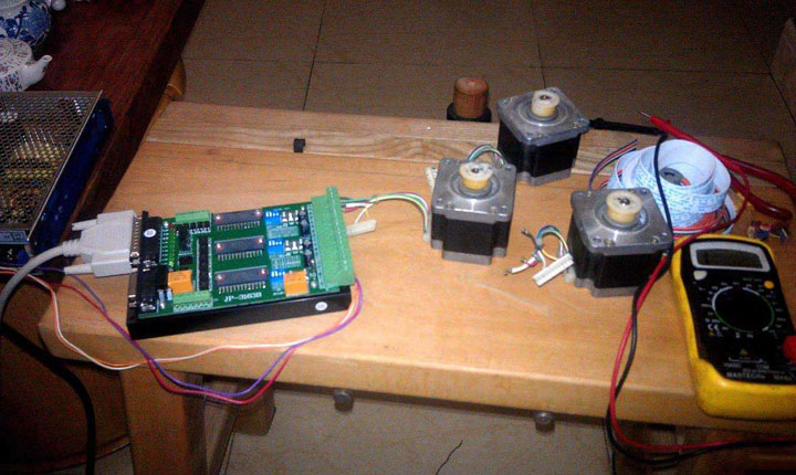
Circuit Part Testing
Connected to the computer and tested it, everything is working well. Of course, before testing, you need to understand how to install and use MACH3.
How to install MACH3 software for CNC router?
1. Open the folder MACH3 in the "MACH3 2.63" directory of the random CD
2. Run "MACH3 V2.63.EXE" to start the installation, click "NEXT" by default until the installation is complete.
3. Overwrite all files in "Overwrite the installation directory" to the software installation path (C:\MACH3 by default), and confirm the overwriting.
4. Restart your PC.
5. After installing the software correctly, you should be able to see the corresponding logo in the device manager of the Windows system, right-click the desktop icon "My Computer", and then click Properties, Hardware, Device Manager, and you will see all devices in the list. If you can see "MACH3 Driver", which is right. If not, you should reinstall the software. Before reinstalling, you should uninstall the original one and manually delete its directory and clean up the registry.
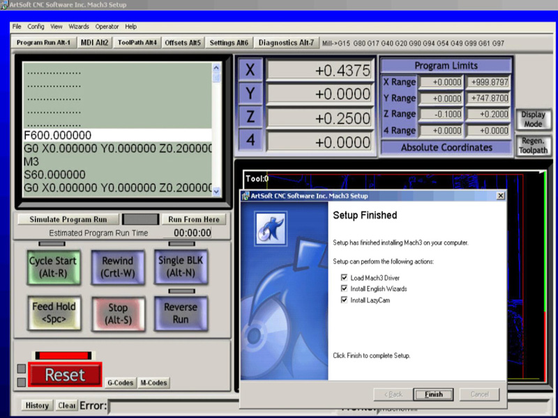
MACH3 CNC Controller
How to setup and use the MACH3 controller for CNC router?
After restarting the computer, there are several new icons on the desktop, all we can use is "MACH3MILL", double-click it with the mouse to enter the CNC control system interface. For how to set up and use the MACH3 controller in details, please do research by yourself, and I won't go into details here.
Step 3. Mechanical Parts Design and Assembly
The building of the mechanical part takes the most time. I bought the raw materials in this order. First, I bought the slider, bearing, and optical axis (because I was afraid that the size of the real object and the drawing would be different, so I got the real object. Measure it again, and later found that it is redundant, because the sliders are all standard), then buy the aluminum sheet for machining, and finally buy the lead screw.
Here is a brief description of the mechanical structure:
The aluminum sheets are made of 12mm thick 6061 alloy aluminum plates. Except for the left and right arms, which are cut, the others are all purchased as standard aluminum rows, which can be used when they are cut. Optical axis is the diameter: Y axis is 20mm, X axis is 16mm, Z axis is12mm, all use hardened optical axis, X/Y axis use linear bearing plus slider, Z axis directly use extended linear bearing to fix on the aluminum sheet, screw use 1605 ball screw.
I have also thought about the processing of aluminum sheets for a long time. Since the left and right arms of the gantry are curved, I do not have suitable tools and they are not easy to process. I can only take it to a nearby shop for laser cutting, drilling, and tapping. If you have metal fabrication equipment, they can also be made by yourself, which can save costs.
After cutting the optical axis and the aluminum parts, sand it with sandpaper, and then wash the oil stains with water, and prepare to start the assembly.
First assemble the Z-axis components, the lead screw and the slider on the back of the Z-axis.
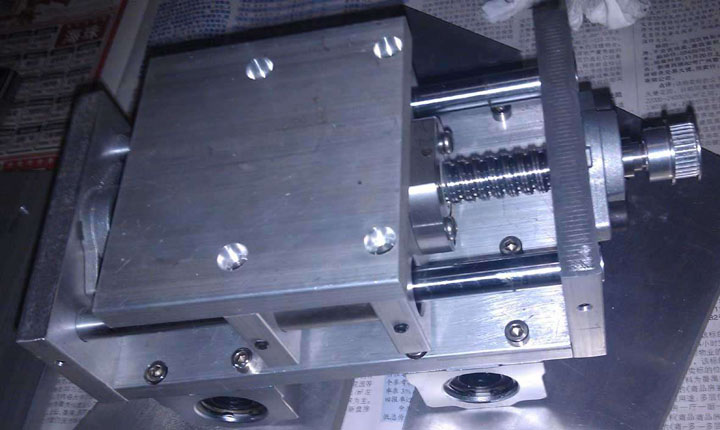
The Main Rack
Since each unit is ready, the overall rack is also easy to assemble, and the following is the effect diagram of the X/Y axis assembly.
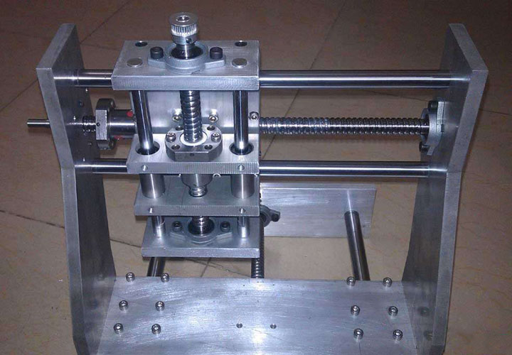
Z Axis Assembly
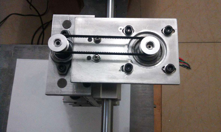
Z Axis Stepper Motor with Synchronous Wheel and Belt
This is the assembly structure of the Z-axis stepper motor. Personally, I always feel that it is too high to put the stepper motor directly on the top, and the whole machine is a bit uncoordinated, so I changed it to the method of using a synchronous wheel and a belt.
The E240 CNC router spindle arrives, and the assembly begins.
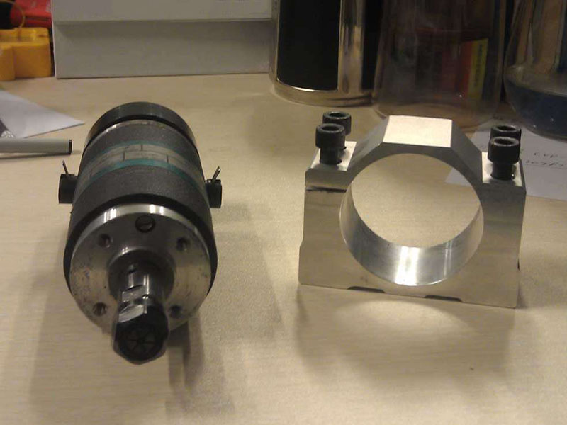
Spindle
Change the direction of the stepper motor, fix it with a brass tube, and assemble the spindle. Is it better looking?
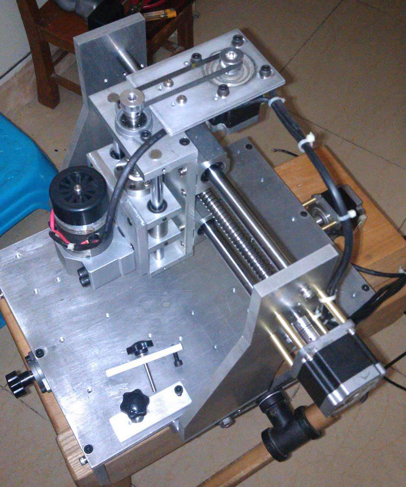
Stepper Motor Fixed
I was so excited at this step, I quickly found the screws to temporarily assemble the X/Y motor, and then tested it with the MACH3 controller. Set the pitch parameters well, and the cut ratio is very accurate. So far the CNC machine is running successfully.
Next, start making your own baseboard
The aluminum plate was sawed when I bought it, and I marked and punched it myself.
After drilling the holes, sand them, clean and assemble.
So far, the preliminary DIY of the CNC machine kit is completed.
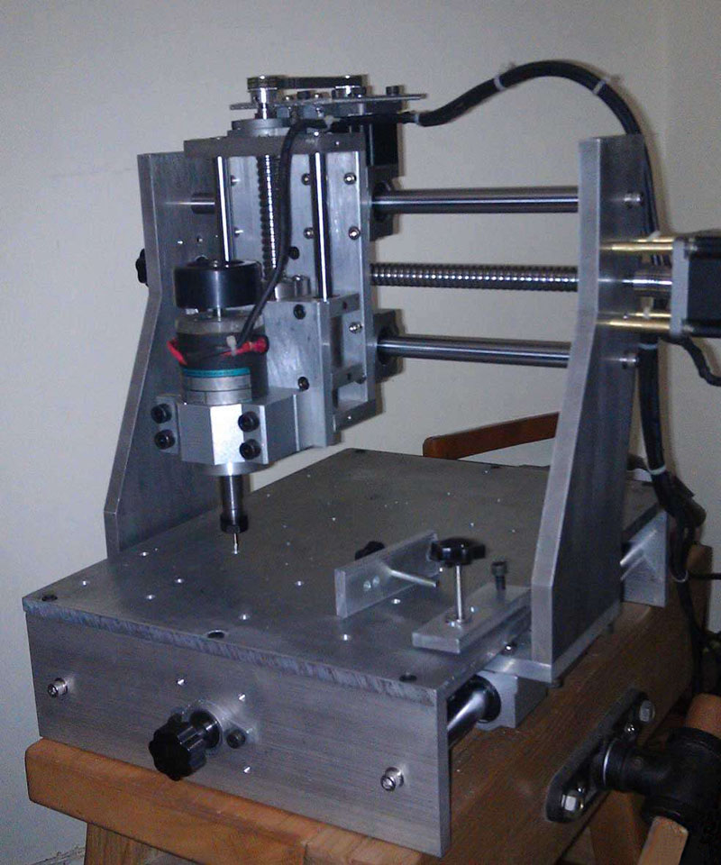
Complete Diagram
Step 4. CNC Router Improvement
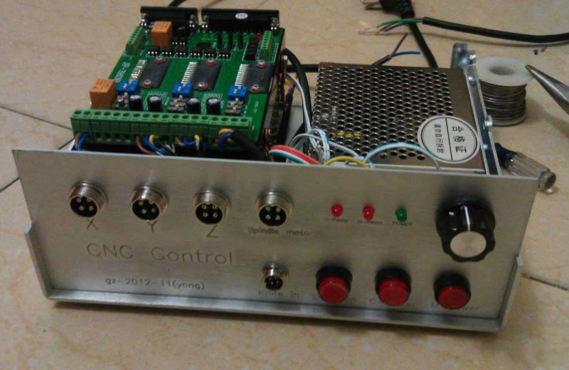
What we need to do for improvement is to make pressure plates, organize cables, and make electric control boxes.
Let's start making the pressure plate, saw the 8mmX300mm aluminum plate into 100mm length, and then punch holes, this is the easiest.
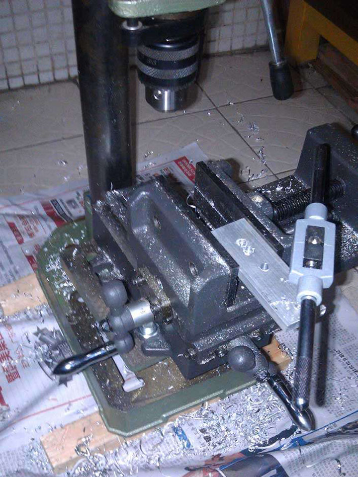
Pressure Plate Drilling
Now I'm starting to make an electric control box. I bought a finished aluminum box directly from the market.
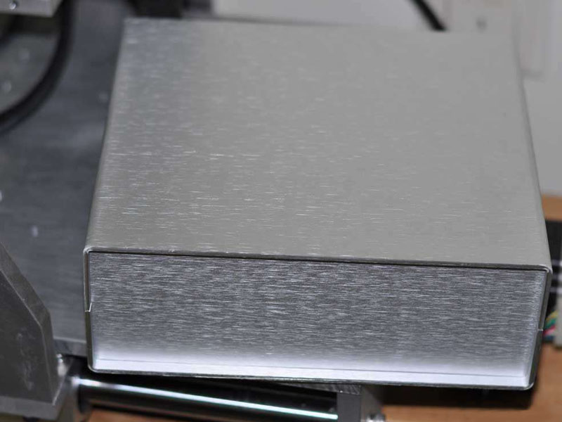
Aluminum Box
Design the control panel in CAD/CAM software, generate the tool path, and start milling.
I used a 0.3 sharp router bit, 30 degrees, and it is estimated that it is better to use 10 degrees to mill.
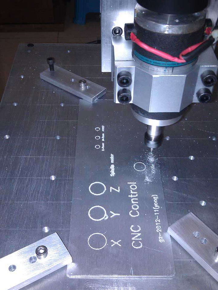
Control Panel Milling
Put on the connector to see the effect.
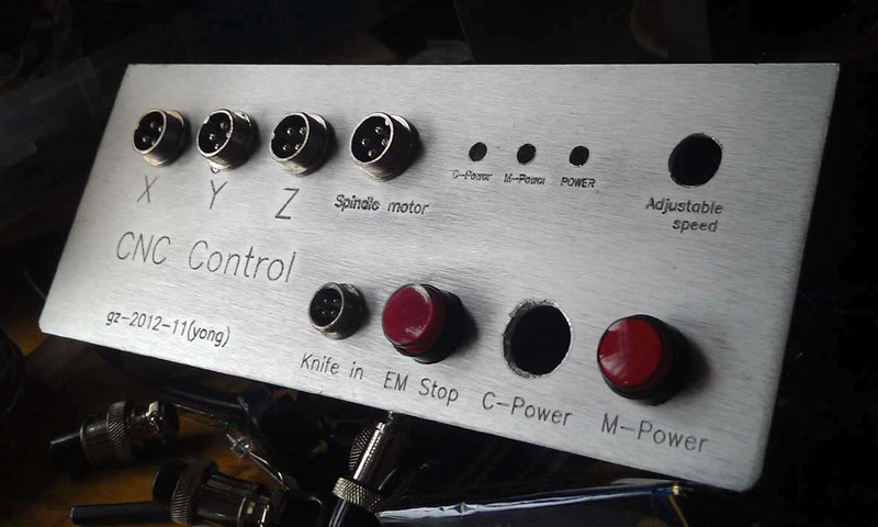
Control Panel Appearance
Start assembling the circuit.
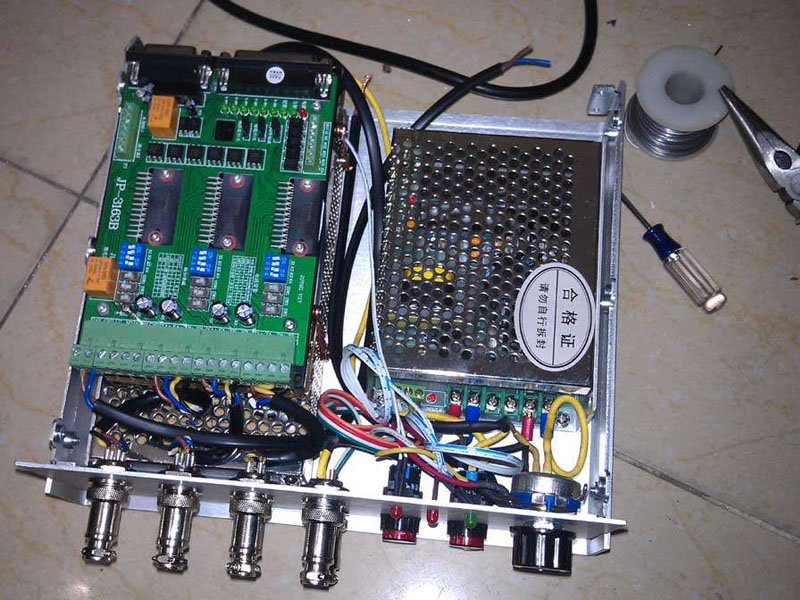
Electric Control Box Internal Diagram
Final Renderings
At this point, the CNC router DIY project is completely finished. In the process of building, I learned a lot of knowledge and experienced a lot of fun. If you are interested, you can really try it out. You will find that you have to keep going throughout the whole making process. Knowing and operating related software, hardware, and CNC knowledge can be said to be a CNC class, which provides a foundation for more difficult DIY plans in the future. Thank you for your attention and valuable opinions, and thanks to STYLECNC. I am willing to communicate with you and discuss things that you are interested in, so as to improve together.
FAQs for DIY CNC Router Kits
Is it Worth to DIY a CNC Router?
If you have the spare time, professional CNC knowledge, enough patience, and an affordable budget, it is worthwhile to DIY a CNC router. If you don't have the ability to build it by yourself, and are still interested in it, you can buy a mini desktop CNC router for hobbyists and home use from Amazon or buy the best budget Chinese CNC router machine overseas at low cost.
How Much Does it Cost to Make a CNC Router by Yourself?
The average cost to make a CNC router by yourself starts around $800, while some can be as expensive as $5,160, depending on the features you need. Different CNC router table sizes (2x2, 2x3, 2x4, 4x4, 4x6, 4x8, 5x10, 6x12) result in different hardware costs. Different CNC controllers can vary the costs of the software.

